Monday, July 18, 2016

Been a while, busy building,  repairing and flying.
Finally got the covering finished on the right wing of  the VP.
Now it's time to create a checklist for the finale.


  1. Cover airelons
  2. Windshield
  3. Cowl
  4. Weight and Balance
  5. Buy second MGL AX2 (Airspeed and ALT COMBO)
  6. Finish rigging controls
  7. And a few other odds and ends, not long now

Sunday, May 15, 2016


Finally getting around to flying my XAIR, long time coming. Hopefully soon I will be posting vids of my VP-2 in the air. 

Tuesday, March 15, 2016

Well...Spent the last couple of weeks learning how to use my new 3D printer.

The majority of the time has been spent setting up, tuning and learning that these things can be fairly complex.

Hopefully soon, I can start designing parts for use in experimental aircraft.  

Saturday, February 20, 2016

Another little project near completion.

Some time ago, while test running my Corvair aircraft engine on my VP-2, I came to the realization that my fuel tank may be too low to provide adequate pressure and for the carburetor.  So..I opted to add a couple of facet pumps in series.  Now, this is all well and good but I had to monitor the fuel pressure some how.  Problems faced;

  1. I didn't want to use a steam gauge for fuel pressure
  • If there is a line rupture; fuel loss and possible fire.
  • ABSOLUTELY no pressurized fuel lines in the cockpit.
  • They are rarely accurate when dealing with low pressures.
      2. After market fuel pressure gauge and senders are outrageous in price.
      3. I needed something that can be customized.

In the end I designed my own.  I found this transducer below, simple, high burst pressure and an active sensor.

Range 0 - 5 psi (0.5VDC - 5VDC)


It's a little on the pricey side, but i liked it and it would work good for what I needed.

Next Step, the display; something small, inexpensive and dependable and made from off the shelf parts.  Arduino, custom PCB and 8X2 LCD.


In the pic above where you see the "XXXXXX", there is room to add another sensor monitor. The PCB has provisions for such a thing. From the top, the screw terminals are as follows:

  1. 12V Neg
  2. 12V Pos
  3. 5V Neg (for power to sensors)
  4. 5V Pos  "                               "
  5. Sensor Input "2"
  6. Sensor Input "1"
This is a very simple, no frill data display.  The design files for the PCB are below plus the Arduino Sketch.  Total price including the transducer, about $60.


As soon as my 3D printer gets here I will design an enclosure for it and share it also.


Thursday, February 11, 2016

   OK....Forget Ethernet, forget Java Script, forget the BeagleBone and SBC's, back-up and start over.  I said it once and I will say it again "KISS"(Keep It Simple Stupid).  And, another DUH!! moment.  I had totally forgot about these guys in Australia; 4D Systems. They make some pretty cool display modules, for what they do, plus the tools available, you can't beat the price.
   After you buy a BeagleBone Black(~$50), The display(~$90), Ethernet Shield(~$15), and less hassle and headache(~$priceless), this display is WORTH IT!!  So...once again...a design change, using a 4D Systems uLCD-70DT-AR , which comes with an Arduino adapter, and an open-source library to talk to the display.  You can't get no easier than this.  I just ordered one from Mouser and I am currently playing with the IDE.  Here is a pic:
More too come.


Slight change in the EFIS & EIS Arduino adapter.


I removed the header for the ENC28J60 Ethernet adapter, and opted for a W5100 Ethernet shield;  since this is only a prototype.  If the design proves successful, all features will be implemented into a single board.  
The prototype as of now consist of the adapter pictured above, an Arduino Mega 2560, then a W5100 Ethernet all stacked atop one another .


Sunday, February 7, 2016

Hopefully, soon, an inexpensive and simple EFIS & EIS


For the uninitiated, Electronic Flight Information System & Engine Information System.

UPDATE:
   Well....I had a big DUH!! moment earlier; instead of going through the pain of developing a cross platform application for this EFIS.  Why not just serve it from the Arduino...so this is the route the project has taken now, using HTML5 Canvas and Java Scripts.  More updates coming soon.


Some time ago, while working on my VP-2; I noticed that the cost of flight instruments is outrageous!  So, I had the idea to build my own as many of us do.  Basically, here is my outlined requirements for such a creature.
  • Simple
  • Inexpensive
  • Portable, Can be used with more than one Aircraft, Very Low Power usage < 1 Amp @ 5 VDC
  • Off the self components
  • Multiplatform
And, here is what I have so far:

Adapter to use an Arduino Mega, for Flight and Engine
8 Analog Inputs, for VDO auto sensors or Active sensors
8 Thermocouple Inputs
Tach
Airspeed
Altimeter

Now for the display; Maybe any type of computer can be used, No Tablets, currently I am using a Beagle Bone Black for development, 8" touchscreen.  The Arduino and the app use ModbusTCP for communication.

Here are screenshots of the app, both the main screen and the settings screen:


This may look big in the pictures, but on an 8" screen, it's quite small.

Tuesday, January 26, 2016

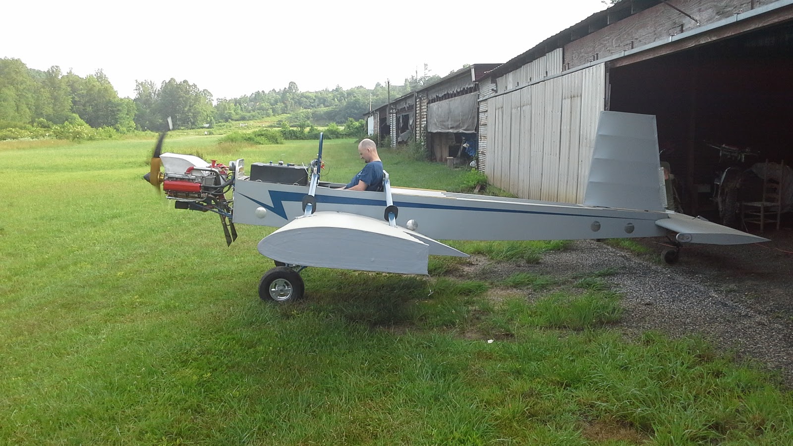
Ok, Here are some pics of the few additions I have added to our X-Air.


Here is My interpretation of In-Flight Mixture Adjustment for 2 stroke flight engines.

These are the sources of my inspiration:

Green Sky Adventures HAC

Jack B. Hart FireFly site

Thanks to Jack for sharing his work, helped me a lot.

1. The carbs have to be re-jetted for your most lean condition.
2. For me I use 165 mains, and had to re-pitch me prop, which gave me ~1200 EGT, 6000 rpm, static,
    OAT ~40F.  Cruise 5000 rpm, ~1150 EGT, much better performance in cool weather.
3. The orifice was trial and error; I used several plastic vacuum tees; filled one side with JB weld and drilled
    them out with different sizes from .040 - .090.  I found that the .060" worked best.
    The orifice has to be small enough for the vacuum to overcome it, and large enough so the vacuum will not     kill engine at low rpm.
4. One has to be careful, I noticed that if the needle valve is turned out, and the orifice is too small,
    IT WILL KILL THE ENGINE AT LOW RPM!!!
5. My system has only had ground test, no in-flight test has been done yet.  Ground test have shown to be         successful in warmer weather.

Needle Valve

Bowl plumbing

Vacuum port in the back

Now, pics of the new antenna mount:
I used split collars from McMaster Carr.  These are
1" collars, but worked well on the metric tubing. 


Windshield bracketing, I LOATH using wire ties to hold a windshield on.  Also, split collars and Adele Clamps.


That's it for now; more later.


Saturday, January 23, 2016

Current and ongoing projects

At the moment, here in NC;  we got 8 inches of snow (I know it's not that much).  And, now that I am older than I was a while back; I care nothing for braving the cold.

Here is the short list:
  • Open Source and inexpensive EFIS for Experimental Aircraft
  1. It uses a BeagleBone Black, running Debian Linux
  2. 4D Systems 7" lcd Cape
  3. Custom Flight and engine sensor boards coming soon.
At the moment the EFIS is still on the bench while I try to learn to write code a bit better, update soon to follow
  • Volks Plane II
Right now, seeing how it's winter time, we are not doing a lot outside.  The right wing panel is ready for paint, and the left panel is still in the rafters.  Along with a few other odds and ends, hopefully it will be ready by next summer.


  • X-Air Standard
We picked up this X-Air about a year ago,  we have added a few upgrades here and there

  1. AirCom antenna based on Dean A. Scott's design (Thanks Dean)


The bracket in the pic's has long since failed, and has been redesigned, more pics later

  • Custom Pitot/Static


That's about it, I will post more when I get around to it.